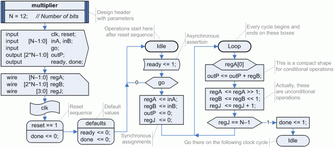
First of all, let us show again previous 'multiplier' design: at the first state, named 'Idle', it waits for a 'go' signal to store the unsigned values received through two 12-bit inputs and then begin operations;
meanwhile, it generates a '1' on its asynchronous 'ready' output to indicate that it may receive new operands. On the second state, named 'Loop',
it executes twelve conditional additions and several shifts in order to evaluate the result: 'outP = inA * inB'. At the end it signals
a valid result using the output 'done', asserted high during one clock cycle.
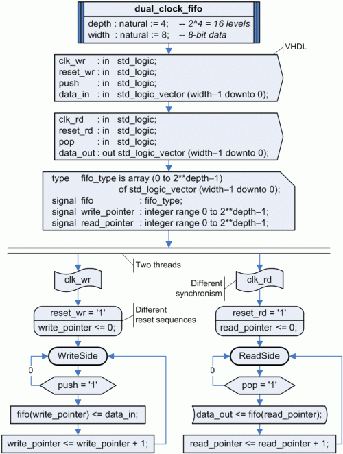
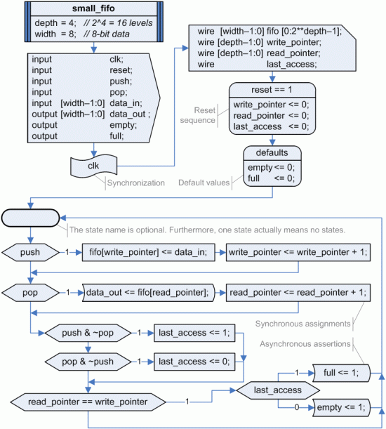
The following figure shows a small FIFO (First In - First Out) memory, a design with also synchronous and asynchronous signals,
no need of any state machine but a complex behavior: at any clock cycle new data can be received through 'data_in' and, at the same time, stored data can be read using 'data_out';
two flags, named 'empty' and 'full', inform outer circuits about the FIFO internal state.
It illustrates the implementation of dual-port synchronous memories and the use of 'empty' states: the state name is only required
when another state box is used as a link to such state (as 'Idle' state above); when state boxes are left empty, ASM++ compiler gives them unique names
to avoid inconsistencies. However, in this case the state machine is finally removed by the compiler, because it has only one state.
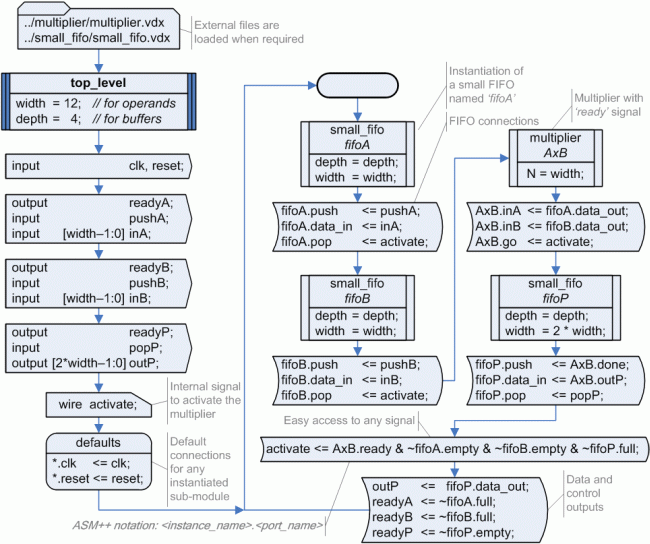
ASM++ charts allows hierarchical design: several charts may be included on one or several files and then each lower-level module can be
instantiated on higher-level designs. The figure below shows a 12x12 multiplier with two small FIFOs (16x12) for
its inputs and an additional FIFO (16x24) for its output. This module has been built using previous modules, 'multiplier' and 'small_fifo'.
This example demonstrates that ASM++ is an OAOO technology:
designers are required to write what they want to do once and only once; VHDL and Verilog are a bit different at this point.
The following figure illustrates an outstanding feature of ASM++ compared to traditional ASM and also FSM: two or more state machines can be described
on the same design, running in parallel, and sharing the synchronization or using different clock signals. In this example, VHDL has been
used all the expressions of this diagram; thus a VHD file will be produced by the ASM++ compiler.
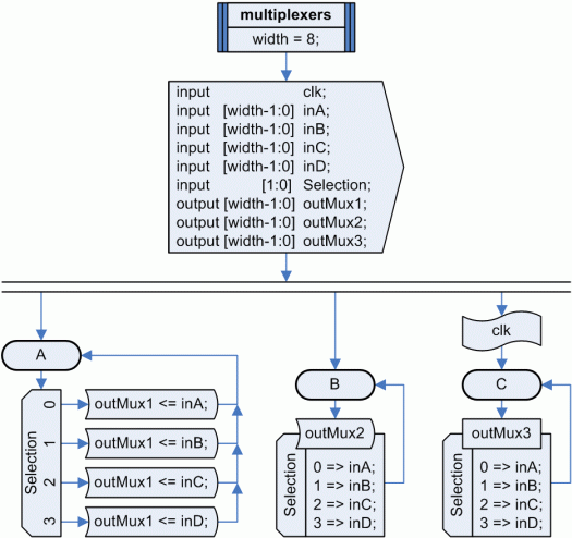
The last figure below shows three 4:1 multiplexers: at the left thread, named "A", an asynchronous multiplexer is described using a 'switch' box;
on the thread "B" there is an equivalent design using a more compact 'AsyncTable' box; the last thread "C" shows a synchronous version
of the same 4:1 multiplexer using a 'SyncTable' box.
This figure suggest a great advantage of ASM++ charts over classical ones:
the use of a specific box for states not only separates different cycles in a clear and intuitive fashion,
but also frees rectangular boxes related to operations to be used for more complex situations.