| epYme documentation |
|
ASM++: a modern Algorithmic State Machine methodology for RTL designs
ASM++ elements
![[<state name>]](images/Box_State_en.png) |
"State" boxes identify the beginning and the end of each clock cycle.
They may indicate the name of a state or designers may left them blank for automatic name generation.
They can also be used as links between distant parts of a diagram.
All ASM++ charts must have at least one of these boxes. |
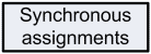 |
In these boxes multiple operations can be written, but they will be executed simultaneously
when finishing the current clock cycle. Expressions used on these boxes
must complain all rules imposed by standard VHDL or Verilog. |
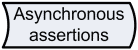 |
In these boxes multiple operations can be written, also using VHDL or Verilog,
but they will be executed in parallel during the current clock cycle.
Any signal can have a synchronous or asynchronous behavior, but not both. |
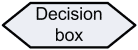 |
"Decision" boxes allow to establish two alternative ways based on a condition.
At any clock cycle, one of both ways is selected, thus deciding which operations are
going to be executed during that cycle.
When a path inside a state specifies two or more different operations for the same signal,
only the last one is actually considered. |
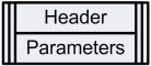 |
This box specifies the name of each module/entity and, optionally, several parameters/generics that
would be changed later when instantiating this component into a higher level design. |
![(vhdl) <port name> : {in,out,inout} <port type>; ...
------
(vlog) {input,output,inout} [range] <port name>; ...](images/Box_Inputs-and-Outputs_en.png) |
This box is used to define the inputs and outputs of a design.
When the number of ports is high, or when they can be grouped somehow,
several boxes of this kind are recommended. |
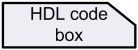 |
These "code boxes" are used to write compiler directives (preceded by a '#' symbol)
and direct source code (VHDL or Verilog), for example to describe internal signals ('signal', 'wire' and 'reg' keywords are currently accepted;
although Verilog users may write 'wire' for synchronous signals, 'reg' is also allowed).
It is convenient to locate the code box related to each signal where expected: immediatelly before
those boxes that assign them a value, or at the begining of the thread that defines its behavior,
or at the begining of the module. The ASM++ compiler accepts them even if they are located
at the end of other threads, but then diagrams would be more difficult to read. |
![(vhdl) [not] <signal name>
------
(vlog) [!] <signal name>](images/Box_Synchronization_en.png) |
This box establishes the name and polarity of the synchronization signal used by a circuit or a thread.
It affects to all boxes afterwards. |
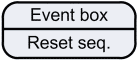 |
This box can be used to specify the circuit behavior when an asynchronous event occurs. Nowadays, this box describes initialization (reset) sequences and the first state of state machines.
These boxes must be located before any state box. |
 |
A "connector" links without further effects two parts of a diagram, in order to facilitate a clear layout.
When linked points are located on the same page, the connector shape must be a 'circle'; an 'arrow-like'
connector must be used between different pages. |
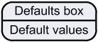 |
This box can be used to specify default values for synchronous and asynchronous signals. They must be used before any state box. |
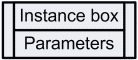 |
This box is used to instantiate a lower level module, defined using another ASM++ chart or even HDL code.
Parameters of instantiated modules may be changed using the lower field. |
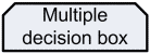 |
These boxes allow to take multiple simultaneous decisions. |
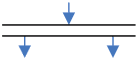 |
A "doble line" stablishes parallel threads, that will be executed in a concurrent way.
This ASM++ feature allows the description of multiple state machines or circuits, with equal or different synchronization.
Once separeted, two threads cannot join again. |
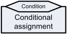 |
This box joins a synchronous assignment box with a decision box. This means that those assignments will be
executed if and only if that condition is true. It allows more compact diagrams. |
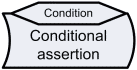 |
In the same way than previous box, this box is the compact shape for conditional assertions. |
 |
This element has no effect on the generated circuit, but can be used to facilitate the interpretation of the diagram. |
Index · Previous: A proposal for ASM++ charts · Next: Examples
|
|