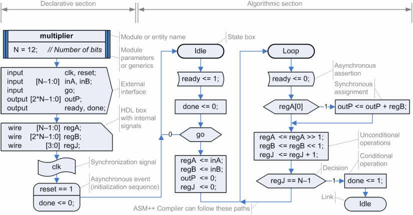
The main difference with classical ASM charts is that a newly created "state box" is used to represent the begining (and the end) of each
clock cycle. It has oval shape, similar to those circles used to represent states in conventional state machines. Thus,
rectangular boxes are now used to describe both conditional and unconditional synchronous operations, and asynchronous assertions
are introduced using boxes with bent sides. Diamonds are kept for conditions.
In addition to the previous changes, new boxes have been added on a "declarative section", as shown at the left part of the figure:
- The design name and its parameters can be defined using a "header box".
- The module interface and the definition of internal signals can be made through a "port box" and a "code box" that use
VHDL or Verilog expressions (like all boxes).
- The synchronization signal has a specific box, and it affects to any box afterwards.
- The initialization sequence can also be completely detailed using its own box.
- Additionally, the state box can be used as a link, making easier the organization of charts and simplifying the interpretation of multi-page diagrams.
The resulting ASM++ charts are not so compact, but they are easier to read and understand, and also they are more convenient for CAD tools.
The ASM++ Compiler can read these charts drawn using MS Visio 2003/2007 and generate the equivalent VHDL or Verilog code, valid for simulation and synthesis.